International Baccalaureate · MYP 2
Solids
I
Pyramids and Cones
Definition — Right Prism
A right prism is a polyhedron that has a uniform cross-section which is a polygon. It has two identical, parallel faces called bases, and all the other faces are rectangles. Prisms are named according to the shape of their base. | Name | Figure | Cross-Section |
| Triangular prism |  |  |
| Rectangular prism (also called a cuboid) |  |  |
The glass pyramid of the Louvre in Paris and an ice-cream cornet are not prisms or cylinders: a right prism keeps the same cross-section (sliced parallel to its bases) all along its length — these two solids do not. 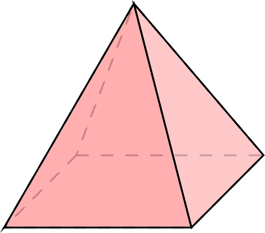 \(\quad\)
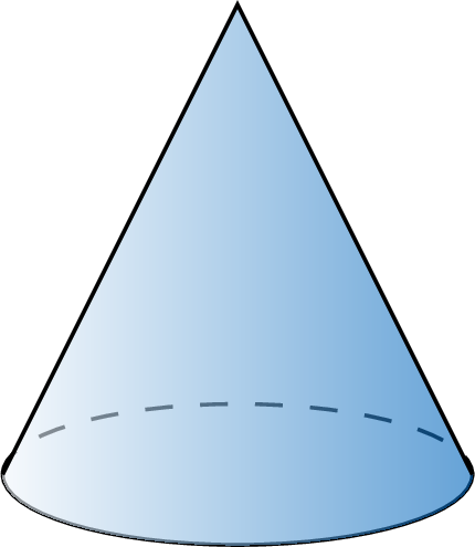
What do these two solids have in common? How are they different?
\(\quad\)
Both solids rise from a base and taper to a single point.
- The Louvre pyramid stands on a \textcolor{colordef}{square} base, and its lateral faces are flat triangles.
- The cornet stands on a round base, and its lateral surface is curved.
Definition — Pyramid
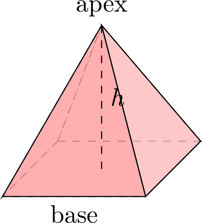
A pyramid is a solid whose base is a polygon and whose lateral faces are triangles that all meet at one common vertex: the apex.The height of the pyramid is the segment that joins the apex to the plane of the base and is perpendicular to that plane.
A pyramid is named after its base: a pyramid with a square base is a square-based pyramid.
Example
Here is a pyramid with a square base. - How many faces does it have? What are their shapes?
- How many edges does it have?
- How many vertices does it have?
- It has \(1\) square face (the base) and \(4\) triangular faces (the lateral faces): \(1 + 4 = \mathbf{5}\) faces.
- It has \(4\) edges around the base and \(4\) lateral edges going up to the apex: \(4 + 4 = \mathbf{8}\) edges.
- It has \(4\) vertices around the base and \(1\) apex: \(4 + 1 = \mathbf{5}\) vertices.
Definition — Cone
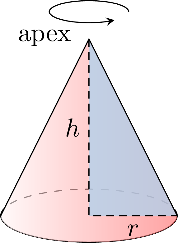
A cone (a right circular cone) is the solid generated by a right-angled triangle rotating around one of the two sides of its right angle. - Its base is a disc.
- Its lateral surface is curved: a cone is not a polyhedron.
- Its apex is the tip of the solid.
- Its height is the segment joining the apex to the centre of the base; it is perpendicular to the base.
Example
A right-angled triangle has the two sides of its right angle measuring \(3\) cm and \(4\) cm. It is rotated around the longer of these two sides. 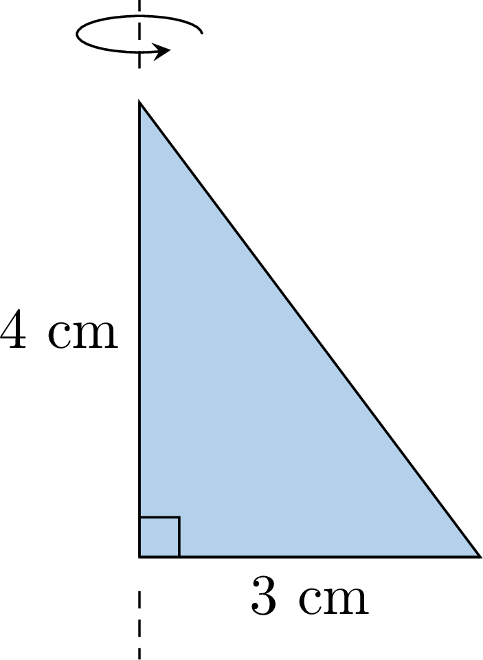
The rotating right-angled triangle generates a cone. 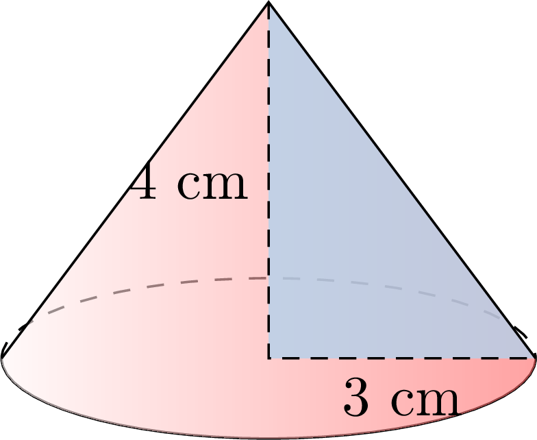
- The axis of rotation is the \(4\) cm side: the height of the cone is \(h = \mathbf{4}\) cm.
- The \(3\) cm side sweeps the base disc: the radius of the base is \(r = \mathbf{3}\) cm.
Skills to practice
- Recognising Pyramids and Cones
- Describing Pyramids and Cones
II
Representing Pyramids and Cones
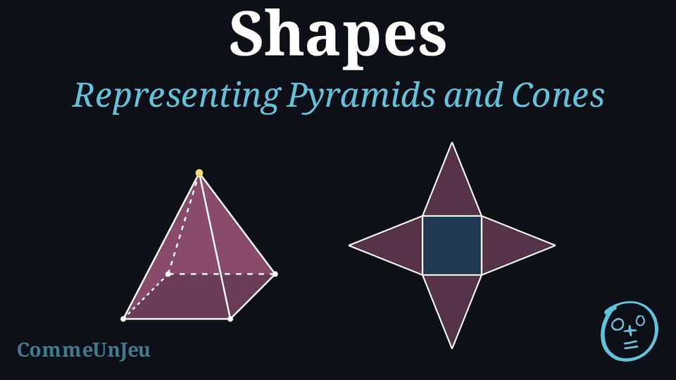
Lea wants to build a small cardboard model of a square-based pyramid. On her sheet, she first sketches the solid to show what it looks like (left). Then she draws the flat piece that she will cut out and fold to build it (right). 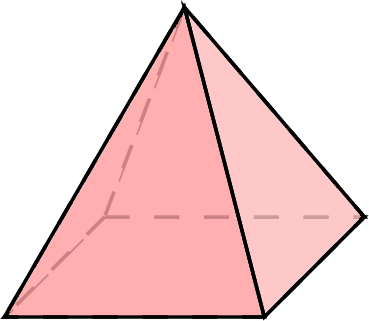 \(\quad\)
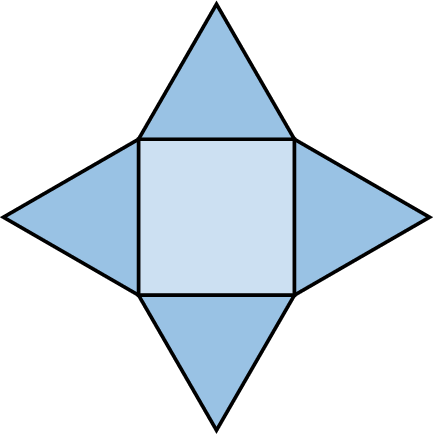
Are these two drawings the same? What is each one called?
\(\quad\)
No, they are different drawings. \(\quad\)
- The first is a sketch in perspective: it gives an impression of depth, with the hidden edges dashed and the square base drawn as a parallelogram.
- The second is the net: all the faces laid out flat, attached along fold lines. Cutting it out and folding it rebuilds the solid.
\(\quad\) Definition — Cavalier Perspective
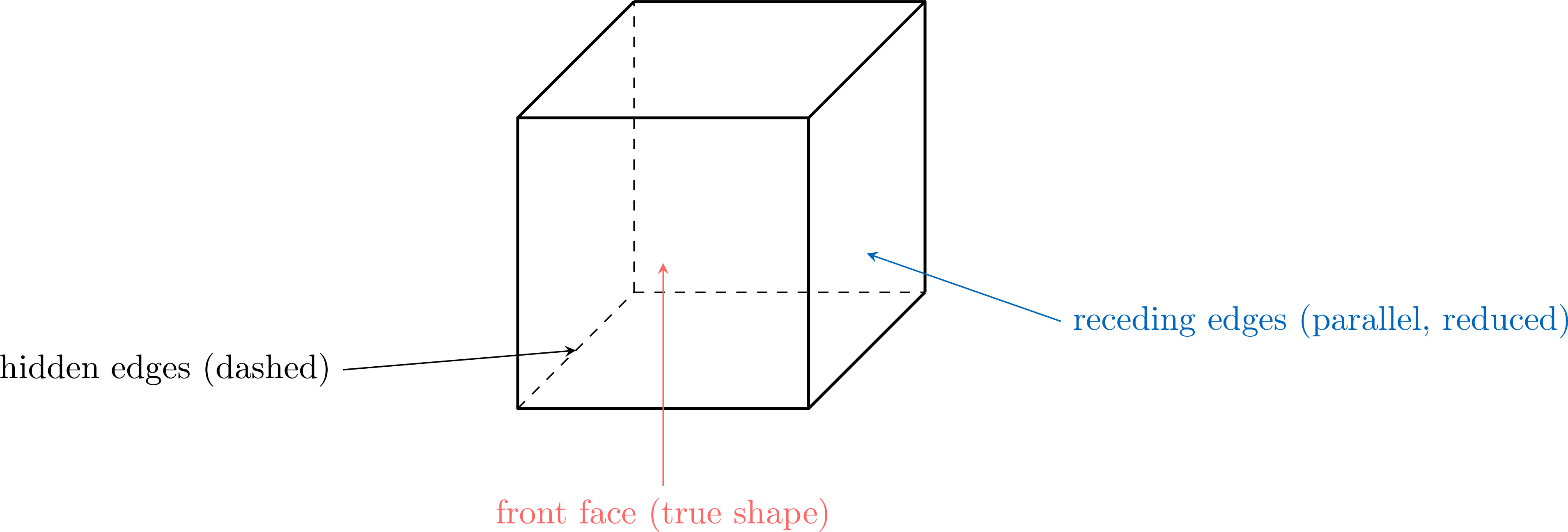
The drawings of solids use cavalier perspective (also called an oblique drawing). Its rules are: - the front face, parallel to the paper, is drawn in its true shape — real lengths and real angles;
- the edges that go away from the reader (the receding edges) are all drawn parallel, at the same fixed angle, and shortened by the same factor;
- edges that are parallel on the solid stay parallel in the drawing;
- edges hidden behind the solid are drawn dashed.
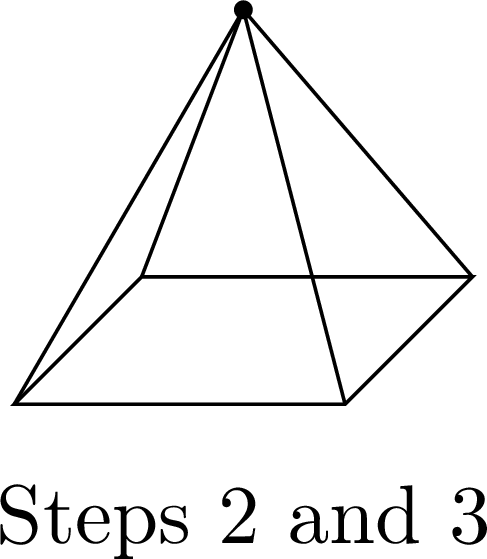
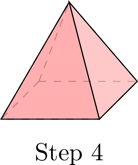
Method — Drawing a Pyramid in Perspective
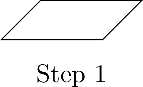
- Draw the base as it appears at an angle: a square base is drawn as a parallelogram.
- Mark the apex above the centre of the base.
- Join the apex to each vertex of the base.
- Go over the hidden edges with dashed lines; the visible edges stay solid.
 \(\quad\)
 \(\quad\)
Example
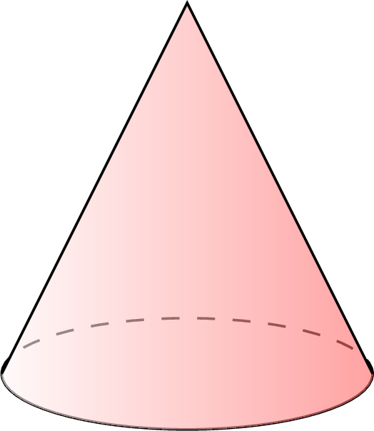
Draw a cone in perspective, and explain the steps. - Draw the base as an ellipse (the disc seen at an angle): the front half is solid; the back half is hidden, so it is dashed.
- Mark the apex above the centre of the ellipse.
- Join the apex to the ellipse with the two outline segments.
Proposition — Net of a Pyramid or Cone
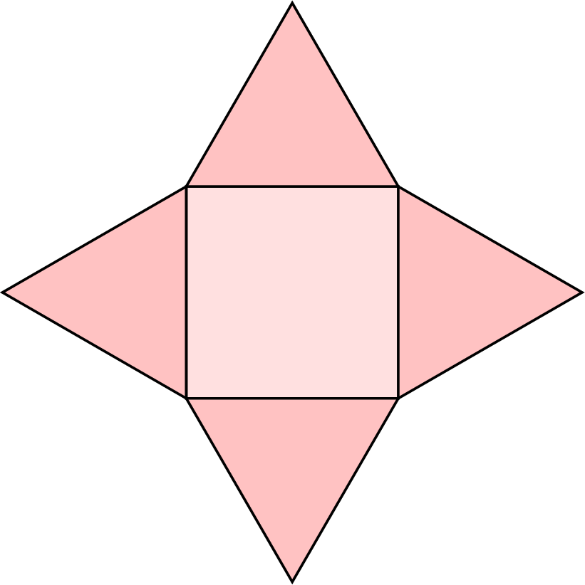
Unfolding a solid flat (after cutting along some edges — for a cone, along a segment from the apex to the base circle) gives its net, as for prisms. - The net of a pyramid is made of its polygon base and its triangular lateral faces — most often drawn attached to the sides of the base.
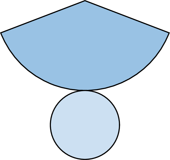
- The lateral surface of a cone is curved, yet it unrolls flat: its net is made of a disc (the base) and a portion of a disc called a circular sector (the lateral surface). When the net is rolled up, the curved edge of the sector wraps exactly around the base: the arc of the sector has the same length as the circle bounding the base disc.
 \(\quad\)
Example
Draw the net of a square-based pyramid whose base edge is \(4\) cm, and whose lateral faces are isosceles triangles with a height of \(5\) cm (measured from the base edge).
The net is made of the square base with the four triangular faces attached to its sides: 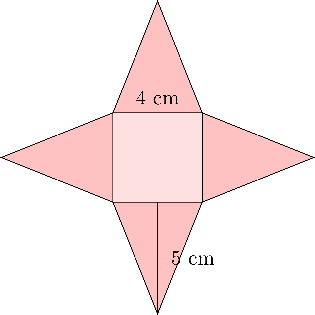
When the four triangles are folded up, their apexes meet at the apex of the pyramid.
- draw a square with sides of \(4\) cm;
- on each side, draw an isosceles triangle pointing outwards, with a height of \(5\) cm.
Definition — Multi-view Projection
A multi-view projection is a way to show a 3D shape using several 2D drawings. Each drawing shows how the shape looks from a different side, such as the front, the right side, or the top. These views help us understand the shape more clearly. Skills to practice
- Identifying a Solid from Its Net or Its Views
- Drawing Solids in Perspective
- Drawing Nets of Pyramids
III
Isometric Drawing
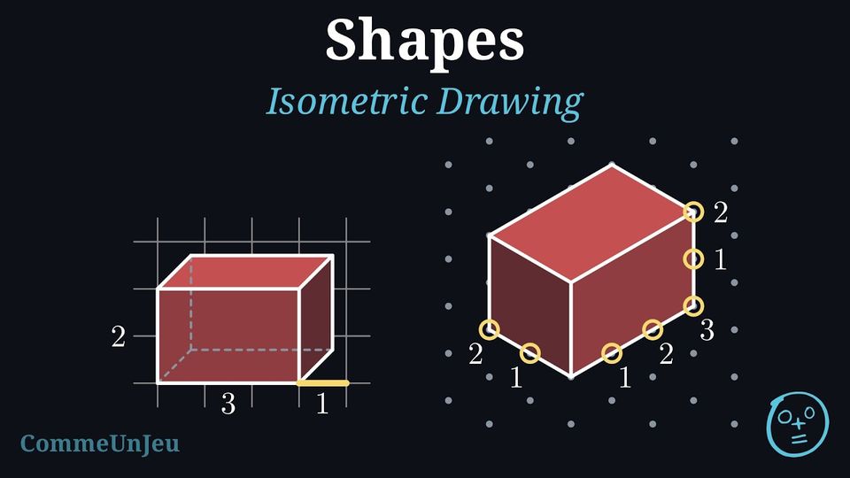
Two pupils have drawn the same box, \(3\) units long, \(2\) units wide and \(2\) units high. Nour used cavalier perspective on squared paper; Tom used isometric dot paper, whose dots form equilateral triangles. 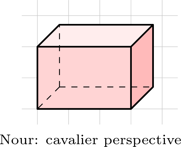
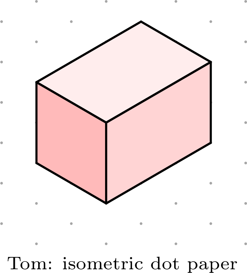
- In which drawing does one face of the box keep its true shape?
- Count the length of each edge in units: the side of a square of the grid, or the distance between two neighbouring dots. In which drawing do all the edges keep their true lengths?
- Tom's drawing is called an isometric drawing: iso means “equal” and metric “measure”. Explain this name.
- In Nour's drawing, the front face is a rectangle of \(3\) by \(2\) squares: it keeps its true shape. In Tom's drawing no face keeps its shape: each rectangle becomes a parallelogram.
- In Nour's drawing, the edges that go back, \(2\) units long on the box, are drawn slanted and shortened, to about half their length. In Tom's drawing, each edge covers as many spacings between dots as it has units — \(3\), \(2\) and \(2\): all the edges keep their true lengths.
- In Tom's drawing the length, the width and the height are measured in the same way: every edge in any of the three directions covers as many spacings as it has units, and none is shortened. Its nearest edge is vertical, in the middle, and the two faces beside it slope away equally on either side: the box is seen from one of its corners.
Definition — Isometric Drawing
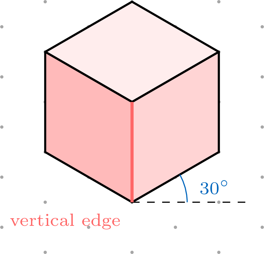
An isometric drawing shows a solid as seen from one of its corners. It is drawn on isometric dot paper, whose dots are the vertices of a grid of equilateral triangles. Its rules are: - the vertical edges of the solid are drawn vertical;
- the edges parallel to the length or to the width follow the two slanting directions of the dots, at \(30^\circ\) to the horizontal; any other edge, such as a slanted edge of a pyramid, joins its two ends once they are placed;
- the length, the width and the height are drawn to the same scale: one unit is the distance between two neighbouring dots;
- edges that are parallel on the solid stay parallel in the drawing; hidden edges are usually left out.
Isometric or Cavalier?
Cavalier perspective (Definition “Cavalier Perspective”) is also called an oblique drawing, or oblique projection: one face is drawn in its true shape, and the receding edges are slanted and shortened. The two kinds of drawing compare as follows.
Cavalier perspective is quick to draw on squared paper and shows one face exactly; an isometric drawing treats the three dimensions of the solid equally, which suits solids built from cubes.
| Cavalier (oblique) | Isometric | |
| Paper | squared | isometric dots |
| Vertical edges | vertical | vertical |
| Receding edges | slanted and shortened | at \(30^\circ\), true length |
| A square face | square or parallelogram | rhombus |
Method — Drawing a Cuboid on Isometric Dot Paper
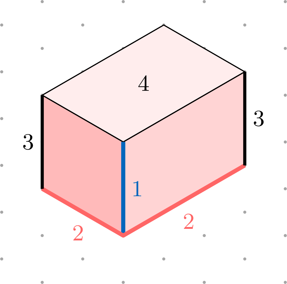
To draw a cuboid of length \(l\), width \(w\) and height \(h\), in units: - Draw the nearest vertical edge: \(h\) spacings, between two dots one above the other.
- From its lower end, draw the two bottom edges along the two slanting directions: \(l\) spacings up to the right, \(w\) spacings up to the left.
- Draw the vertical edges at their far ends, \(h\) spacings each.
- Complete the top face with edges parallel to the bottom ones, then shade the three visible faces.
Example
On isometric dot paper, draw a cuboid \(4\) units long, \(1\) unit wide and \(2\) units high.
The nearest vertical edge covers \(2\) spacings. From its lower end, the length goes \(4\) spacings up to the right and the width \(1\) spacing up to the left; the vertical edges at their ends cover \(2\) spacings each, and the top face closes the drawing with parallel edges. 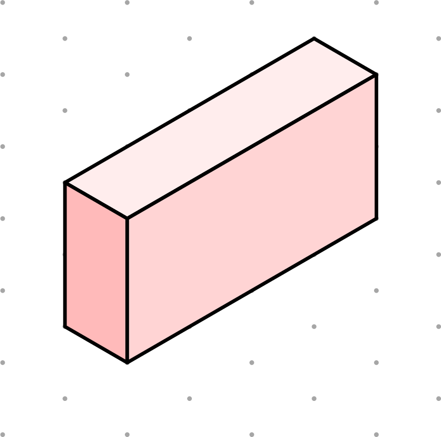
Example
The plan of a solid made of cubes is its view from above; the number written in each square is the number of cubes in that stack, and the arrow shows the front. Draw the solid on isometric dot paper, then find the number of cubes. 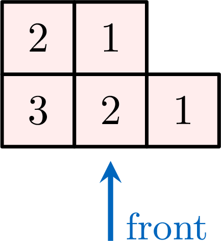
The front row of the plan (stacks of \(3\), \(2\) and \(1\) cubes) becomes the face at the front right of the drawing, running up to the right; the back row (stacks of \(2\) and \(1\)) stands behind it, up to the left. The stacks are drawn from the back to the front, so that the nearer cubes cover the farther ones. 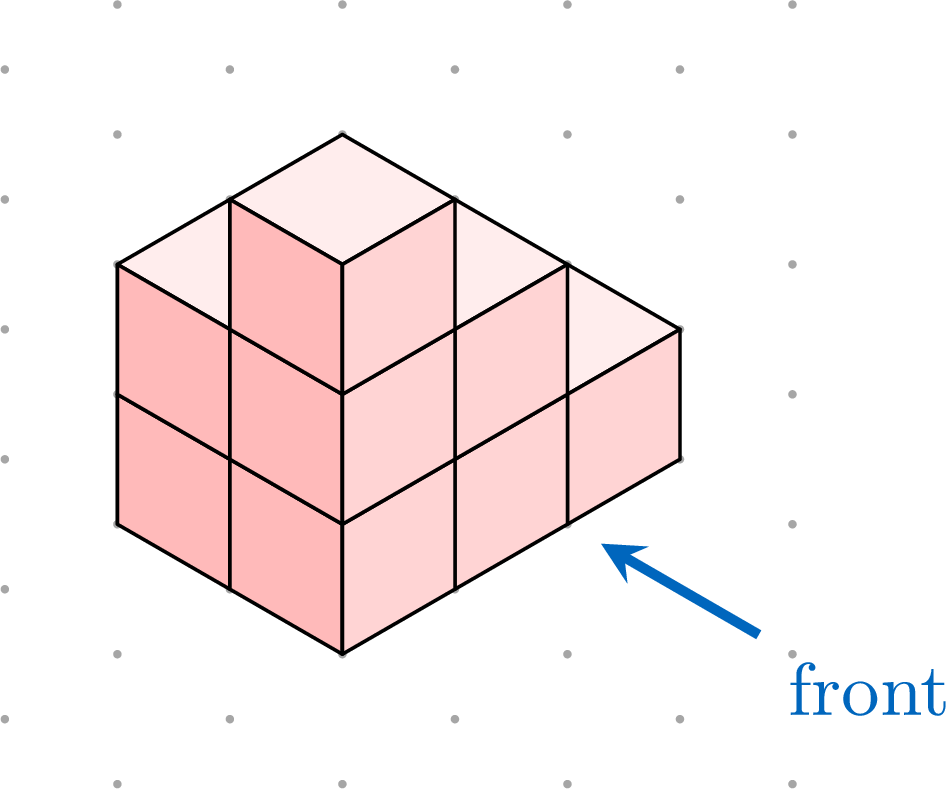
Some cubes are hidden in the drawing, but the plan gives them all: $$3 + 2 + 1 + 2 + 1 = \mathbf{9} \text{ cubes.}$$
Skills to practice
- Recognising Isometric Drawings
- Counting Cubes in Isometric Drawings
- Drawing Solids on Isometric Dot Paper
IV
Going further
Skills to practice
- Solving Problems with Pyramids and Cones
- Investigating Solids Made of Cubes
- Quiz
Jump to section